
Payment and point member | Payment methods | Shipping methods | Warranty policy | Shopping procedure
|
Howdy, this is Mr. Itoh from the service department. And this is my second report. The last time I simply introduced our business operation at the service department. And, this time..well I am already having a hard time to come up with the subject. Well I thought I would introduce the detailed business operation and the inside of the products. But I will do so some other time maybe. Instead I am going to introduce the condenser with the analog tester and the method of checking the quality of the transistor. And at the same time I hope I can write about the principle of operation and the structure of these stuff. There is no special reason why I picked this subject this time. Maybe these are the parts essential for the audio system? Anyway let's learn about these stuff. |
|

|
 |
|
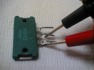
The pictures above are an electrolytic condenser (left picture) and a transistor(right picture). Please forgive me for the unclear pictures. The electrolytic condenser (left picture) is applying the thin insulation film generated from the chemical process on the insulator with electrolyte. The capacity means the capacitance. The capacitance is the ability of saving electricity in the condenser. As you can see on the condenser in the picture, MF (micro farad) or PF (picot farad) is usually used as a unit indicating the capacitance. The condenser consists of 2 sheet-to-sheet metal sheets sandwiching the air or the insulator. The bigger the dimension, the bigger the capacitance. And the larger the distance between the 2 metal sheets, the smaller the capacitance. On the other hand, if a metal sheet is smaller the capacitance gets smaller. And if the distance between the metal sheets is smaller the capacitance gets bigger. The transistor in the right picture has three legs which called base, collector and emitter from the left. And 2SA1094 is written on the front. "2" means effective electrode 2+1, semiconductor for "S" and PNP type high frequency for "A". First of all, let's check out the condenser. What we use here is the Nichicon electrolytic condenser with the capacitance of 470MF, the withstand pressure of 50V and the temperature of 85℃. |
|

|
 |
|
Please look at the above picture on the left. First I set the analog tester range to 10Ω, put the black lead stick onto the + side of the electrolytic condenser and the red stick onto the – side. And then the needle goes to the – side for a second as in the right picture and goes back all the way afterward. |
|

|
|
|
Please take a look at the two pictures. This time the lead sticks are put oppositely from the last time. Put the red stick onto the + side of the electrolytic condenser and black stick onto the – side. The swing gets bigger a little bit from the last time but gradually returns back all the way, which means this is a good-quality condenser. The needle of the poor-quality one has an extremely slow swing back or doesn't go back all the way. And since the swing speed of the needle is faster if the capacitance is large, we need to check the tester range to x 10K, x 1K, x 100, x 10 or x 1Ω accordingly. The black stick of the analog tester has the voltage of +1.5V and passes an electric current. The charge that has been saved on the + side of the condenser repels each other and the – charge on another metal sheet repels each other, so the charge goes back and forth between the polar plates. This is the discharge. This is why the needle of the tester swings for a moment. Charging starts after the discharge. Then the condenser starts saving charge. This is why the needle of the tester returns all the way back. The reason why I put the testers other way round is because that + and – charge saved on the 2 metal sheets after the first charging and discharging and the second charging got switched with one another. After all, it's just a repeat of the same thing. Therefore it becomes easy to pass the alternating current signal through the condenser, which means it becomes easier to pass high frequency through the condenser. I know it is kind of difficult! Next let's check the quality of the transistor. |
|
|
 |
|
What I check here is the Toshiba 2SA1094 transistor. Why did I choose this one? Well because that was just beside me. The transistor is called "stone", and there are A, B, C and D stone. "A" and "B" stones have basically the same structure of the PNP type and are jointed with the PN junction by sandwiching N with another P type semiconductor. "A" stone is for high frequency and "B" stone is for low frequency. And, "C" and "D" stones are NPN type looking like it is sandwiching P with N type semiconductor. "C" stone is for high frequency and "D" stone is for low frequency. Like I wrote about the electrolytic condenser, + charge goes to the black lead stick of the analog tester and – charge to the red one. You can check the quality of the transistor of the "A" stone by checking the electric continuity since the connection between the collector and the base and the emitter and the base is a diode connection. First set the tester range to x 1Ω, put the red stick onto the base as in the left picture and put the black stick onto the collector. Next, put the red stick onto the base and the black one onto the emitter in the same manner. If the transistor is good in quality, the needle of the tester is sure to show the same resistance value. This is because the tester checks the electric continuity with the diode connection described before. To put it more clearly, diode is the material of a connection (PN joint) of the P type semiconductor and the N type semiconductor. The P type semiconductor holds + electricity (called hall) and the N type semiconductor holds – electricity (which is electron). When adding the electrical pressure from the analog tester, in other words, connecting the black lead stick onto the P type semiconductor and the red one to the N type semiconductor, + and – electricity gravitate toward one another because + electricity from the black stick repels each other and – electricity from the red one repels each other. And then the current flows over the joint part. The direction where the current flows is P→N. The current flows from the position where the voltage is high to lower-voltage position. Furthermore, the direction of the hall in the bracket above is defined as the direction of the current flow. |
|

|
 |
|
In addition, you can check the amplifying operation of the transistor at the same time when checking the quality. For PNP, connect the red stick onto the collector as in the left picture and the black stick onto the emitter. The needle of the tester will not swing for sure. If the needle swings at this point, the transistor is not good in quality. Next, put your finger as shown in the picture not to short-circuit the base and the collector. Then the larger the current amplifying rate goes, the greater the needle of the tester swings. As for the C or D stone of NPN, you can only need to reverse the polarity of the tester for a diode connection to a check on the amplifying operation. |
|
|
What did you think? Did you understand it? I think it is quite difficult to understand about the current and voltage since you can not really see them. But I believe that you can get a better understanding by practicing the content written here of the instruction rather than trying to understand in your mind. So hang in there! |
|
 Used
Used Consigned
 Hold
Hold Reserved
 Sold Out
-
-

- Company profile
- Privacy policy
- Contact
- Newsletter back issues
- Hi-Fi Do live camera!
- Today's software
- Today's hardware
- New arrival alert system
- Japanese
-
Hi-Fi Do Online Newsletter
-
Payment methods

-
Shipping methods

-
Warranty policy

-
Shopping procedure

-
Hi-Fi Do Record Shops Softs, Audio parts and Tubes can ship overseas.Ordinary,we use EMS but for large order,we use SAL or Surface.For Asia,it cost 1,200JPY/1LP,900JPY/1CD.Please check at the shipping cost table for more detail.

-
Meaning of icons
