
Payment and point member | Payment methods | Shipping methods | Warranty policy | Shopping procedure
|
Howdy, how is it going with you? This is Ito from the service dept. Last time I wrote about the principle of the operation and method of checking the quality of condenser and transistor. How did you like it? I tried to come up with the topic again for this time, and now I am really bothering my brains. I bother my brains every time though... Anyway this time I will reveal the full truth about a complete repair of Pioneer M-73 and focus on the operational mechanism/structure of the output power relay. |
|

|
 |
|
As you can see the left picture, the electrolytic condenser has been replaced. They were replaced because the electrolytic condenser was deteriorated after years and may cause a liquid leakage or less capacity. When the capacity decreases, the volume feeling in bass decreases and the sound will easily skip. Unlike the film condenser, the styrene condenser and so on, the oil condenser and the electrolytic condenser leaks electrolytic solution to outside and the capacity decreases. Therefore the big capacity condenser near the power source and the swollen condensers have been mainly replaced. The one in the right picture is the main circuit board after the replacement. I know it's not clear enough though. Soldering the condenser is pretty in-depth despite the fact it looks easy. The point to be noted is to pour a necessary amount at a time without soldering it for a long time as much as possible. And do not move the lead wire while the condenser is being warmed, because it is likely to be transformed inside. You must not move it for about 10 to 20 seconds. And then, be careful not to give any big shock from the outside. Then you should never make any mistake with the polarity when installing the electrolytic condenser. Next, let's move on to the relay stuffs. |
|

|
 |
|
Now I will explain about the relay. You may have no idea what the relay is actually even if you look at the picture. I guess you have an experience of hearing the sound like "click" a few seconds later after the power is turned on. That is what it happens when the relay functions. "Relay" is defined as follows. "Relay is electric equipment which has the function to control On-Off of the other electric circuits by identifying the presence, the size and the other forms of electric power energy prescribed beforehand." In short, Relay in general means the electromagnetic relay which means an electric part controlling On-Off of the switch by using the electromagnetic power. To understand the basic structure of the relay, please take a look at these two pictures. The one in the left picture is the output replay of M-73 and installed still on the circuit board. I think you can get a better understanding with the right picture which shows another output relay. As you can see in the right picture, the coil is winded around a bobbin-like stuff. And there is an iron core in the center of that coil. Furthermore, I will explain about this with another different relay picture. |
|

|
|
|
In this picture you can't see the coil though, the coil is winded and there is an iron core in the center of it. And, there is an armature whose supporting point is the end of yoke connected to the iron core. The traveling contact moving with the armature is a dot striking a golden gleam in the picture. (Am I getting you confused?). And facing the traveling contact, there is a fixed contact. The gilded part on both sides of the traveling contact is the one. The relay consists of a spring called return spring that operates(moves) the armature from the fixed contact. When having the direct current flow, the iron core in the coil generates magnetism and becomes an electromagnet. (Maybe you experimented in the science class?) Through the yoke(right-angled metal piece), the flux of magnetic induction is generated. And the armature and the iron core face get magnetized to the opposite pole respectively, and the armature gets sucked toward the iron core face. At this time, the relay becomes ON since the traveling contact is being contacted to the fixed contact since the traveling contact moves with the armature. At this time, the return spring in the picture gets stretched. When there is no current flow through the coil, the relay becomes OFF since the armature is away from the iron core due to the power of the return spring. Naturally the relay gets deteriorated after the relay gets attached or detached back and forth like this. The deterioration in the relay performance is mostly due to the failure resulting from the sulfuration of the contact point or dust. Uncommonly, the coil may get short-circuited due to the bad heat radiation of relay or around relay. Anyway this time the traveling contact wasn't burned. Instead they just cleaned the contact point since it was so dirty. |
|
|
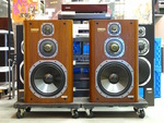
Finally the repair of M-73 completed. There is a knob installed for switching speakers. The power meter lamp makes me feel warmhearted somehow. I haven't turn on the power yet though… Next, let's check and see the waveforms. |

|

|
 |
|
I checked with the small output of 1K hertz 40dB oscillator by putting the pseudo-resistance of 8Ω and by turning up the oscilloscope output up to 5mV/DIV. But despite that, it shows such beautiful waveforms. There is no distortion in the waveforms. I was impressed. The waveforms in the right picture are the one showing the frequency characteristics. This one is flat and fully covering the bandwidth in audibility. Then when I actually listened to the sound through a CD, I was impressed by the volume in low region and the sharpness in high region, even though the sound has a little bit of stiff feeling. This item was being aged for two days and now it is available at the store. So please try the sound. Anyway I must get going around here this time. |
|
 Used
Used Consigned
 Hold
Hold Reserved
 Sold Out
-
-

- Company profile
- Privacy policy
- Contact
- Newsletter back issues
- Hi-Fi Do live camera!
- Today's software
- Today's hardware
- New arrival alert system
- Japanese
-
Hi-Fi Do Online Newsletter
-
Payment methods

-
Shipping methods

-
Warranty policy

-
Shopping procedure

-
Hi-Fi Do Record Shops Softs, Audio parts and Tubes can ship overseas.Ordinary,we use EMS but for large order,we use SAL or Surface.For Asia,it cost 1,200JPY/1LP,900JPY/1CD.Please check at the shipping cost table for more detail.

-
Meaning of icons
