
Payment and point member | Payment methods | Shipping methods | Warranty policy | Shopping procedure
|
Howdy, this is Ito from the service department. Thank you always for subscribing our email magazine. I am running out of topics already...Like always, I bother my brains about the subject I need to write this time. This time, I will simply explain about the content of repair of Sansui Electric "AU-D607F EXTRA" and the waveform seen in the waveform observation. Well then, here we go! |
|

|
 |
|
This is the overall picture of SANSUI "AU-D607 EXTRA". Normally the model number is on the main body and the center of the front part. The black exterior case creates an extraordinary atmosphere. The main features are tone-control, bass and tremble control, subsonic function which removes noise in extra low-region, muting switch, changing-over switch for speaker and so on. And here are the contents of repair. |
|
|
First we replaced the electrolytic condenser which is a bypass condenser in the main amp. There was more replacement in number than you see in the picture. |

|
|
This item came in our store because it was making too much noise. Other than that, it was encountering a lot of failures such as DC leakage and defective switches at the same time. I wanted to explain about these failures in more depth, but I will do so some other time in the future. Anyway let's move on to the main topic of today, the waveform observation. |
|
|
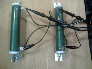
Now what do you think it is? This material body is a resistance of 8Ω load, which is called pseudo-resistance. In short, it is a replacement for a speaker. The voltage at both ends of this resistance is received by probes and outputted to the oscilloscope as a waveform. |
|

|
 |
|
Now, let's actually see the waveform of this pre main amp through the pseudo-resistance. See the output of the 1k? sine-wave at 0dB of attenuator from the oscillator received by the pre main amp with the oscilloscope through the 8Ω load resistance. The vertical axis in the picture is the output (voltage) and the horizontal axis is the time base. Both of them are related to the frequency. In the picture there are two pairs of peaks and troughs. But the number of these peaks and troughs will increase when the frequency is raised by the oscillator. Peaks and troughs are not smooth in the left picture. This condition is called clipping in which the output is exceeding the performance limit of the amp. The amp is screaming. If this condition lasts for hours, the amp will get broken of course. The vertical amplification (vertical axis) of the oscilloscope is set to 5V/DIV now, which means that 5V per grid is being outputted. So you can see the super high output voltage coming out. Once this happens, the equipment becomes hot very quickly and the pseudo-resistance also generates fierce heat. The waveform in the right picture is a sine-wave of 24v=72W as the output alternating voltage value. You cannot see any distorted waveform in the picture at all. The cooling wheel is already hot at this point. The output stage transistor may be screaming... Next, let's see the waveform through the tone circuit. |
|

|
 |
|
The indicator in the left picture lights in red since it is through the tone circuit. The tremble volume in the left picture has been raised up to the maximum. And its state is shown as a waveform in the right picture. This is the waveform where high region is added to the square wave. And a rise of the waveform is extended means that it includes the high frequency component. |
|
|
That's all for today. Next time, I would like to talk about the waveform in more depth. Well excuse me, I got to go now. |
|
 Used
Used Consigned
 Hold
Hold Reserved
 Sold Out
-
-

- Company profile
- Privacy policy
- Contact
- Newsletter back issues
- Hi-Fi Do live camera!
- Today's software
- Today's hardware
- New arrival alert system
- Japanese
-
Hi-Fi Do Online Newsletter
-
Payment methods

-
Shipping methods

-
Warranty policy

-
Shopping procedure

-
Hi-Fi Do Record Shops Softs, Audio parts and Tubes can ship overseas.Ordinary,we use EMS but for large order,we use SAL or Surface.For Asia,it cost 1,200JPY/1LP,900JPY/1CD.Please check at the shipping cost table for more detail.

-
Meaning of icons
