
Payment and point member | Payment methods | Shipping methods | Warranty policy | Shopping procedure
|
Hello. It is my turn again after two weeks. This is a report by Ito at the service department. Last time I introduced a cleaning method of the contact point for output relay. Was it helpful for you? Sorry for talking about a pre-main amp every time, but I report this week again on a pre-main amp. I would like to report on other audio equipment as well in the future. So, the topic is also on a SANSUI pre-main amp AU-D607G EXTRA. |
|

|
 |
|
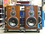
This pre-main amp was delivered from Nihonbashi Store for repair (left photo). Since the malfunction was described as "Unexpected DC voltage," I immediately measured approximate voltage using a digital voltmeter (right photo). The voltages were 60mV or more on the left channel and 50mV or more on the right channel. Surely these were high voltages. However, the DC voltage of a SANSUI pre-main amp is highly variable and we cannot get stable data unless we measure after a certain warm-up time. So I measured again after warm-up, but obtained the same DC voltages. If there were really unexpected DC voltages in the amp, what was the cause of them? As you may know, "DC voltage" stands for direct current voltage. If this voltage should be unusually high, the speaker will likely become broken. The role of protective circuit and a protector is to catch a high DC voltage and turn off the output relay. But a DC voltage that can make the speaker broken is a fairly high voltage. |
|
|
In order to find out the cause of the trouble, I connected the body to an oscilloscope and checked waveforms at a CR oscillator. Then in addition to the "Unexpected DC voltage," I found out irregular waveforms concerning variable resistors and selectors. Furthermore, sometimes there was no output of waveforms. Since I understood the outline of bad condition and its cause, I started to disassemble the amp. First, I removed the top panel. You can get an overview of the circuit on the photo. There were four large electrolytic capacitors. These were filter capacitors to minimize ripple waveforms that were generated at the power supply unit. Since these were located at the power supply unit, both capacity and pressure on them were high. I had to pay careful attention in treating them. Additionally, there were a transformer and radiator in sight. |

|
|
Anyway, I repaired the amp to correct the irregular waveforms of the variable resistors and selectors and the output of waveforms became normal. Let me skip the detailed process of my repair. You can imagine how I repaired, I suppose. Next, let me go ahead with the unexpected DC voltage, the main theme of this report. |
|
|
Please have a look at the photo. This was a semi-fixed variable resistor to adjust DC voltage. By turning it, I was able to balance the DC voltages between the left and right channels. By turning the variable resistor just a little, DC voltage could be widely varied. So I had to be careful. Ideally, the nearer to 0V DC voltage is, the more stable the amp is. So I adjusted the voltage as near as possible to 0V. |

|
|
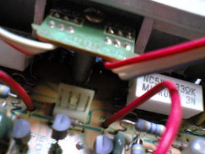
It was also necessary to adjust idle current. Since makers set it diversely in their own way, we had better not modify it in general. However, if the idle current is widely unbalanced between the left and right channels, we need to adjust it. Please look at the photo. There were four pins on the connector. By checking two pins at a time with testers on the left and right sides, I was able to measure the idle voltage. In checking these parts with testers, I had to be really careful. If it had resulted in short circuit, the amp would have become broken. |
|
Additionally, look at this photo. There was another semi-fixed variable resistor, but this one was to adjust idle voltage. I was able to balance the voltages between the left and right channels. |

|
|
Finally, the pre-main amp was completely repaired after these adjustments. It is in aging still now, but its DC voltages are stable and the amp reproduces clear sound. See you again! |
|
 Used
Used Consigned
 Hold
Hold Reserved
 Sold Out
-
-

- Company profile
- Privacy policy
- Contact
- Newsletter back issues
- Hi-Fi Do live camera!
- Today's software
- Today's hardware
- New arrival alert system
- Japanese
-
Hi-Fi Do Online Newsletter
-
Payment methods

-
Shipping methods

-
Warranty policy

-
Shopping procedure

-
Hi-Fi Do Record Shops Softs, Audio parts and Tubes can ship overseas.Ordinary,we use EMS but for large order,we use SAL or Surface.For Asia,it cost 1,200JPY/1LP,900JPY/1CD.Please check at the shipping cost table for more detail.

-
Meaning of icons
