
Payment and point member | Payment methods | Shipping methods | Warranty policy | Shopping procedure
|
Hi, there. This is Ito from the service department. I have some feeling that a turn has come in no time. Well, I pick up an article of a vacuum tube power amplifier and introduce repair contents and the check method easily at this time. |
|
|
|
|
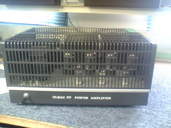
This photograph shows a 6L6GC push-pull vacuum tube power amplifier. To tell the truth, my knowledge is likely to be equal to an ignorance, but tried to take it leave at this time. |
|
|
 |
|
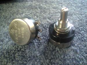
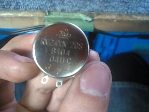
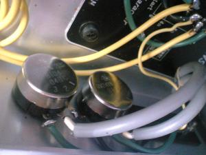
The thing in the photograph is the volume to be changed at this time. Oh! It is gotten neatly what it is. I'm very pleased with that the picture is taken clearly. There is a high-quality feeling in the volume, isn't there? But how it is? The right photograph was taken from the backside of the volume. It is a B curve. Three terminals appear, but a number is written down with 1,2,3. Two of the middle is the place for output. 1 and 3 become both ends. As for the explanation of the volume, please read a former e-mail magazine for your reference. |
|
|
 |
|
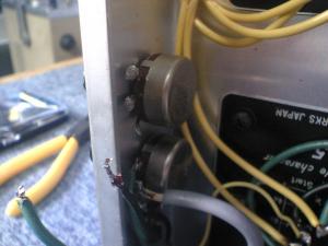
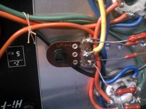
Well, which is the volume before exchanged? It is clear at a glance as you see. For wiring, green is 3, black 1, and 2 of the output is white. Solder them well not so as to make a mistake of right and left in reverse! And be careful not to put a soldering iron for a long time and put solder too much! Oh, it must be without question. |
|
|
Now, this is a bonus. This is an adjustment volume for keeping the DC balance. (May be hard to look). As it is similar to transistor, it is an ideal that bring close to 0mV if possible, but it is OK at around 60mV because it changes in the situation of a ball every moment. Feel the area between plates of a push-pull with a tester and adjust it with a minus driver. Be careful not to short-circuit. Do not turn up the volumeat a stretch! You should pay utmost attention. Further more, there is bias adjustment, but I will still omit it this time as my knowledge is vague and doubtful. In addition, I think I will explain it at other opportunities. |
|
|
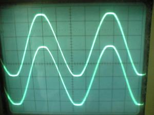
Let's see, I tried to check a wave pattern with an oscilloscope this time. In the case of a vacuum tube, got out volume to the maximum and made it clipping. It should be good if the clipping was in right and left in the same way. Because the load resistance was 8Ω if the VAC showed 16V when I did clipping, and which meant the output of 32W was to appear by calculating it briefly. Furthermore, the output became around 22V when it raised the voltage! 60W! A vacuum tube met our expectation. Even if it had extortion, it did the best. But, there was a limit not to do it, so do not for a long time. And, with a transistor, you should not do absolutely in a similar thing. A transistor is different from a ball and it betrays our expectation of unconcernedly. Of course it does not do the best. It will be blown at a stretch. And when you put up load resistance, be careful of the power because the thing I use has an ability for bearing even 100W. |
|
Well, I shall close now. See you again. |
|
 Used
Used Consigned
 Hold
Hold Reserved
 Sold Out
-
-

- Company profile
- Privacy policy
- Contact
- Newsletter back issues
- Hi-Fi Do live camera!
- Today's software
- Today's hardware
- New arrival alert system
- Japanese
-
Hi-Fi Do Online Newsletter
-
Payment methods

-
Shipping methods

-
Warranty policy

-
Shopping procedure

-
Hi-Fi Do Record Shops Softs, Audio parts and Tubes can ship overseas.Ordinary,we use EMS but for large order,we use SAL or Surface.For Asia,it cost 1,200JPY/1LP,900JPY/1CD.Please check at the shipping cost table for more detail.

-
Meaning of icons
