
Payment and point member | Payment methods | Shipping methods | Warranty policy | Shopping procedure
|
Hello, how have you been? This is a report by Ito at the Service Dept. It is nearing the end of 2005. Above all, it is too cold outside! Please take care not to catch cold. Then I report this week on how I replaced the old attenuators of the JBL Model 4343 with new ones. |
|

|
|
|
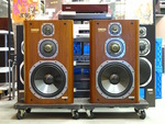
Shown on the photo is the JBL 4343. It was brought to the Service Dept. Because of malfunction of the attenuators, so I replaced them and repaired. The unit was removed. At any rate, I had to remove the attenuators shown on the center of the photo. The attenuators were from left for mid range, high range and ultra-high range. In order to remove the attenuators, I had to remove the plate at first. The attenuators were firmly fixed to the cabinet with screws. It took me so long to remove the plate, as you see the reason right away looking at the next photo. |
|
|
This photo showing a process to remove the plate, but it is not easy to understand though I used the words "right away." Let me explain in short. Something purple shown on the right of the photo is a hair dryer, and a metallic material shown on the lower center is a spatula. I made use of tools for daily use. As you see on the photo, in order to remove the plate I inserted the spatula into a narrow opening between the cabinet and plate and began detaching the plate. But why did it require a hair dryer? This was because this plate was firmly stuck on the cabinet with adhesive. So I heated the plate and metallic spatula by the hair dryer and softened the adhesive. This process required patience and concentration as well as carefulness and skillfulness of hands. If I had carelessly inserted the spatula and forcibly tried to remove the plate, it would have been bent and never been restored. So I was under a lot of pressure. |

|

|
Ha! This photo showing the cabinet after I removed the plate. Do you see the mark of the adhesive that shows how it was troublesome to remove the plate? A wooden board of the same size as this mark was fixed on the other side of the cabinet with screws. |
|
This photo shows the whole appearance of the attenuators, which was detached from the main body having screws removed. Then it was time to replace attenuators. But to be noted here was that I had to remember the wiring of the attenuators exactly before I detached them, needless to say. Furthermore, it was necessary to adjust the height of shafts even. I adjusted the height by using nuts, etc. |

|

|
 |
|
After the replacement of the attenuators, the next process was soldering. To be noted was that I did not keep the soldering iron touching the attenuator so long to avoid burning it. In addition, I was careful not to use so much solder. It was no good to use so much solder because excessive solder would flow on the terminal and damage the carbon inside. Next, I soldered the both sides of each terminal so that the solder would cover the whole terminal. The photo shows the opposite side of attenuators after soldering. The smallest attenuator was for ultra-high range. A close-up of it is shown below. |
|

|
How does it look? You may see all the wires were firmly soldered. |
|
This time I reported from a different perspective. Is it helpful for you? See you next time! |
|
 Used
Used Consigned
 Hold
Hold Reserved
 Sold Out
-
-

- Company profile
- Privacy policy
- Contact
- Newsletter back issues
- Hi-Fi Do live camera!
- Today's software
- Today's hardware
- New arrival alert system
- Japanese
-
Hi-Fi Do Online Newsletter
-
Payment methods

-
Shipping methods

-
Warranty policy

-
Shopping procedure

-
Hi-Fi Do Record Shops Softs, Audio parts and Tubes can ship overseas.Ordinary,we use EMS but for large order,we use SAL or Surface.For Asia,it cost 1,200JPY/1LP,900JPY/1CD.Please check at the shipping cost table for more detail.

-
Meaning of icons
