
Payment and point member | Payment methods | Shipping methods | Warranty policy | Shopping procedure

|
My treasure, "Tube amp making course" By Otomeijin(September 30, 2005) Chapter 3: Let's make it! Vol. Exciting practice (Part 1) So far, we understood about the important soldering for the electricity-related outline concerning the amp or the amp making. So we get into the practical chapter from now on. We use the kit from "Sun Audio" in this course but I imagine there are people using the other kit or virtual(?) kit. The shapes, location, values or quantity of the parts would be different respectively though, the process and the points to be noted are all the same. So let's learn all together. I will mention what you can't learn from class in a timely manner. |
|
We get into the making process finally, so please prepare a working space, a worktable and so on. Of course we sit on a chair to work, so the height of the worktable should be a little short. Since you need an enough space to put a soldering iron or any parts beside the chassis of 36 cm in width, you may need a table of 60 cm in width at least. You also need to put the drawing documents nearby. Oh! Please put your coffee cup on the other side. Ideally the outlet of the soldering iron could be tabletop type. Because when you put the iron on the table, the iron is likely to drop from the table onto the floor since the iron is lighter than the cord and pulled down by its own cord to the floor. And, no cigarette please. When you get engaged in making the amp you would forget to smoke, and then, cigarette/tobacco whatever gives off fumes around. This secondhand smoke harms your health and the amp. (+_+) Maybe it's a good time to quit smoking on this occasion? This is the recent "fashon" in the amp world. Can you imagine a contact point dirty with tar? What would JAZZ fans say about it? |
|
|
Anyway we go on to wire with reading the instruction manual and the wiring diagram in this kit. I won't really talk about the tools etc. Maybe only a driver, nippers, tweezers, radio pincers, a soldering iron and a tester. 1. "Preparation" of accessories We need to prepare accessories in the way I talked in the special soldering lesson. (The order in the "assembling manual" will be changed a little bit to the "Otomeijin" way since there is no explanation about how to solder in this kit.) First we remove the bottom lid by putting the whole chassis flipped over with a cap attached so as not to damage the transformer installed in the kit. At this time, don't install the "vacuum tube" yet. And please do not let any bulging part of a switch or terminal touch the table because it is kind of heavy. |
|

|
 |
|
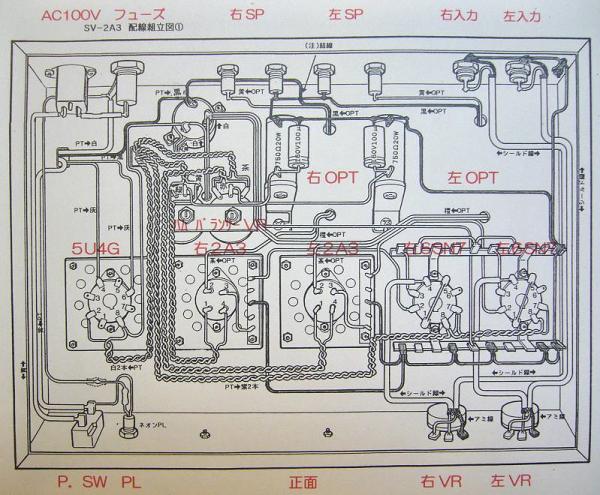
The inside layout looks like the one on the wiring diagram (1) (in the picture). First untie the lead wire of the transformer to drop it down on the front, and then, be sure to fully "plate" the part terminal installed already from its edge so as not to damage it by keeping away from it. (in the second picture) Probably you understand after you do that, the part terminals get pretty dirty with the solder flux steam, dirt etc. So clean it with a Q-tip every time you find it dirty. And please don't get confused since each part is arranged respectively from left to right as viewed from the front. From now on you are the one making the amp, so please go ahead with a self-supervised check-up as in plating, marking of wiring-finished signs, etc. All roads lead to a "success". It is not surprising that you want to keep some documents for the maintenance after you have made the amp. So please do so in your own fashion. |
|
|
|
|
Just in case, I just put on the circuit diagram fixed in red according to the wiring diagram. It doesn't mean that the original one is wrong but just not enough. It'll be very user-friendly if they update it. As you can see the connection line on the circuit diagram, the place of ● the black dot mark on the intersecting point of lines is not a connection. This is the rule on the 2D diagram. Basically the T intersection is a connection. In general, ○ the white dot mark indicates a terminal. |
|

|
|

|
 |
|
Now I will talk about the terminal of the vacuum tube socket here. The terminals where the foot of the vacuum tube can fit in are evenly installed in the socket mold. Please bend them in the direction where you can make clearance between the terminals for the GT tube socket except 2A3 as if flowers bloomed. You need to bend the terminals on the input earth wire side, the one-point earth lug and the VR terminal as well, so as to solder them easily. But be sure not to short-circuit by bending too much. In all the soldering process from now on, please be careful not to short-circuit them each other by bending too much or making a long plated area after peeling too much, or with little strings or drips from soldering. |
|

|
 |
|
2. First of all, wire lead wires of the transformer as in the assembling instruction (1). But please do not throw away any extra lead wire cut off. It will be used later. Here is the point to be noted. You will have some extra lead wires for the voltage not used in the transformer which is not external tap type(in short, the lead pullout type transformer like the one I am having here now). But you might need them later since the characteristic of the amp can be changed by replacing the vacuum tube when it comes to Sun Audio Kit. So don't scrimp but make sure to put them together after insulating the terminals so as not to short-circuit them. There were 6 lines (2 for PT, 4 for 2OPT) for the whole transformer. Well they should have written this kind of stuff in the instruction manual, don't you think? As for the wiring color, there is a certain rule industrially. But I just specify on my own that red is for high voltage DC, white or yellow for 100V or low voltage AC and black or blue for earth wire. - Wiring on the PT primary side: Wire for 100V for commercial use, AC socket, PW switch, neon PL, PT and fuse. (See the picture below.) Since the neon tube will light up when the voltage comes, please put it on the PT lead wire side in yellow. This neon tube will stay lit all the time on the AC100V hot side. When wiring for fuse, please pull out the fuse plug before soldering just in case so as not to blow the fuse. - Finish up around the rectifying tube. Do not forget to wire for plate. Connect the block condenser of the pie-shaped rectifying circuit with CH (It is called B power supply). - Wire for heater of five vacuum tubes. Since this kit is using the alternating ignition system, twist lead wires for heater wiring so that each lead wire cancels out the electromagnetic induction by "going and returning". It would be difficult to twist tightly as in the wiring diagram though, please make sure not to make it too loose and wire them as if the wires were crawling along the chassis. And, please do not make any mistake in color and direction. Please see the picture for reference. - Let's wire for earth wire. Here I painted the earth wire in black. And I drag around the earth wire off the bottom in the circuit by separating from the chassis. Then I dropped it down onto the chassis at a certain point. (One point earth) This prevents the loop circuit and makes it resistant against induction hum noise and surge noise. I don't know how to figure out logically where this point should be, though, generally it seems good to be near the input. Is there anyone who can give me some guidance here? The point is located on the left input side in this kit. It is an external earth terminal. The thick lead wire would be better for earth wire since various currents flow in the earth wire. There was a black lead wire for earth wire in the kit. We use a single naked wire around the speaker and at the earth part of the input part. - Connect the two output tubes to the OPT primary side. Then let's connect the output terminal to the OPT secondary side. I picked 8 ohms in yellow. Please adjust it to the speaker you use accordingly. - Let's wire for two amplifier tubes, power supply system and around the lug terminal. |
|

|
|
|
I changed the wiring route as in the picture for 6SN7 the furthest heater because I didn't like the fact that purple lead wire was shorter than I expected and the amplifier stage grid wiring was crossing the heater. Will this change turn out good or bad? (I am embarrassed with this kind of non-quantitative talk though…"Better keep away from danger") |
|

|
|

|
|
|
- Let's work on the signal wire going to the grid from the input pin via VR. It is the last work in this paragraph 2. Here we use the shield type cord to protect the signal wire from noise. I will explain more since this cord needs a terminal treatment different from the lead wire I talked about so far. The core of the shield wire is usually covered by the mesh-like wire that becomes an earth wire, and the shield wire is wrapped around with the insulating material. Peel the coating off by inserting a knife all around at the point of 15 to 20 mm away (to be able to reach between signal hot terminal and earth terminals) from the edge of the shield wire without cutting the mesh-like wire. And then make clearance in the mesh-like wire with tweezers etc. to pull out the core to separate each other. After you peel the core about 5mm off, you do the "preparation". (See the 4 pictures below for the treatment procedure.) Please twist up the mesh-like wire and do the "preparation" at the tip of it to make it flexible. Then make sure not to short-circuit it with the core. Now let's connect it while measuring and cutting each wire and treating the terminal according to the real stuff. The core wire is only for the grid side and the earth wire is for VR side. The ancillary shield wire is thin in the core and the Teflon coating on it is too hard to bend flexibly. I wonder why they make like this wiring diagram. Maybe they want to take advantage of that characteristics, though, the stress loads on the core after soldering. So I am worried if it snaps due to a secular change after years of use. I would like them to review it to change. |
|

|
 |

|
 |
|
3. Confirm the wiring: It is OK even if the wiring order is not exactly the same as the above. But it would be better to wire from the back with seeing the wiring diagram. Please prevent the alternating current part and the direct current part from being translational or approaching each other. That's all to cover the wiring diagram(1). I don't put up all the pictures of each part, though; please complete it likewise properly with seeing the overall picture. Up to this point, it kind of looks like the amp even though the parts like resistance haven't been installed yet. Anyway my wiring work is kind of ugly for being as Otomeijin, though, it's been a while since I wired. In the next step, you cannot fix the lead wires since the parts will be installed over them. So make sure to double check if there is no wiring mistake or no missing wire by putting checkmarks on the circuit diagram while viewing the wiring diagram. Well now it's a perfect time to take a coffee brake. |
|

|
|

|
|
|
How are you doing so far? I changed some from the instruction manual though, I think that doing on your own way is one of things that you can enjoy yourself in making the amp. And I'm glad that I have finally made it to this point. Although I didn't think that my presbyopia was that bad before starting, my presbyopia led to more inefficient and poorer soldering work than I imagined. Unluckily I had to deal with a replacement of my computer and a preparation of digital camera, while struggling to make a deadline. And it seems that I am causing trouble to Hi Fi Do. Well, I am sorry that it will take another more lesson than planned for this course. I will talk about the wiring for resistance etc. next time. To be continued. |
|
 Used
Used Consigned
 Hold
Hold Reserved
 Sold Out
-
-

- Company profile
- Privacy policy
- Contact
- Newsletter back issues
- Hi-Fi Do live camera!
- Today's software
- Today's hardware
- New arrival alert system
- Japanese
-
Hi-Fi Do Online Newsletter
-
Payment methods

-
Shipping methods

-
Warranty policy

-
Shopping procedure

-
Hi-Fi Do Record Shops Softs, Audio parts and Tubes can ship overseas.Ordinary,we use EMS but for large order,we use SAL or Surface.For Asia,it cost 1,200JPY/1LP,900JPY/1CD.Please check at the shipping cost table for more detail.

-
Meaning of icons
