
Payment and point member | Payment methods | Shipping methods | Warranty policy | Shopping procedure

|
My treasure: "Tube amp making course" By Otomeijin (October 7, 2005) Chapter 3: Let's make it! Vol. Exciting practice (Part 2) Chapter 3 includes many processes, so it is composed of two parts. In this part, let's mount the chassis with such parts as resistors and condensers. |
|
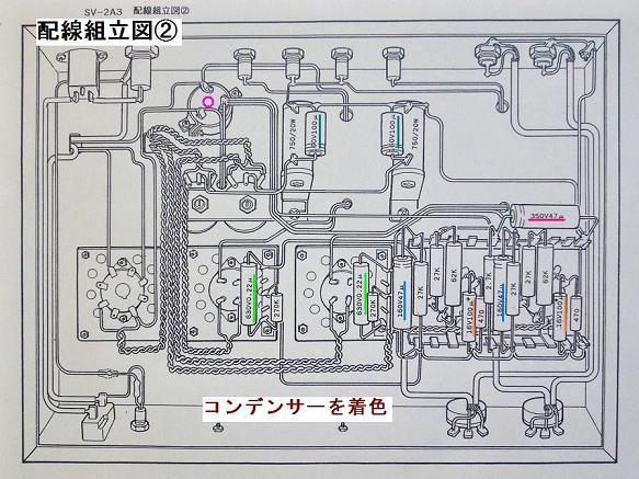
4. Mount the chassis with parts as shown on Wiring Drawing (2). Since you need to fit a narrow space with parts three-dimensionally, you do it mostly by checking to see which part is to be placed where. Besides, you can enjoy the process of wiring to make it good in its appearance as well. As you know, once these parts are electrically connected, the amp will work, and the inside of the chassis cannot be seen from outside. So it is all right if the parts are firmly fixed to the chassis. On the other hand, you may want to do the wiring so that it will be good both in maintenance and appearance without any trouble (actually there are only a few cases of trouble). Although it depends upon your preference, there will be less trouble such as short-circuiting if you place the parts and wires in order. Therefore, do the wiring paying enough attention to that point. Place the lead wires in order by reviewing 2 of this course. Bundle them with attached bands at necessary points. In order to make the wiring good in appearance, wires must cross at right angles with one another. The Wiring Drawing (2) below shows such a way of wiring, so just follow it feeling at ease. Though I forgot to tell you last time, if one terminal is attached with more than one wire or part, combine the wires and parts together beforehand by twisting the wires together so that all of them can be attached to the terminal at one time. (See the Special Course for Soldering on Sep. 23.) On the contrary, if you solder them one after another, the previous solder may melt and slide or fall. By looking at the Wiring Drawing (2), decide by yourself how to take measures. Here we are in the most exciting process! |
|
|
|
|
5. Clues to wiring Make sure you take preventive measures against "yaki-tori" (scorching the parts) in the following work process. Taking into account the following precautions for this process, attach all the wires and parts to the chassis based on the Wiring Drawing (2). Precautions: Place the resistors in an airy space because they become heated, while the condensers are weak against heat and must be placed below the resistors (above the resistors while doing wiring) so as not be heated by the resistors. On the Wiring Drawing (2), one of 160V47μ condensers is misplaced, so correct its position. Every part must be placed so that it will not touch one another and that it will not touch the back lid which is to be attached to the chassis later. Since you must solder each part to a terminal in a narrow space, be careful not to have the solder iron touch the other parts. But if you detach the solder iron from the part too early, the part may not be firmly fixed to the terminal but just be placed on it. Check to see if the solder on the part has fused into the solder on the terminal to become fixed. Since you need to solder in a narrow space, combine a resistor and condenser together tentatively beforehand as shown on the photo below so that you can easily solder them in one set to the terminal. It will let you solder more smoothly. Let's try. |
|

|
|
|
Have a look at photos below of each wiring section. Although there are many experts of soldering, Otomeijin's work is on such a level. Compared with long time ago, it was a painstaking work for me this time to do the wiring because my eyes were dim with age. In my early days, I even attached a diamond stylus to a cantilever! Thanks to my digital camera that I bought for extra equipment, my photo-making time was shortened. Blur-adjusting function of this digital camera is helpful to an old man like me. When I was young, I was able to keep my camera motionless in my hands for a second or so. Without a viewfinder, I had to confirm an image on the LCD (liquid crystal display) screen of the camera by putting on and taking off my glasses. With this trouble regarding a digital camera without a viewfinder, some day a sturdy single-lens digital camera may be produced. Oh, I have deviated from the main topic! |
|

|
 |

|
 |

|
|
|
6. Check the wiring As you did last week in this course, check to see if all the wires are connected to terminals correctly. I also checked carefully by myself and found out a misplacement of a condenser's cathode in the first section of the wiring. I turned it over, but I had to place the part slant because the length of the lead wire was different. If I had turned on the switch without correcting the misplacement, the amp would have been broken. Watch out! Make sure that any part does not touch another! Finally, clean out carefully useless pieces of cut wires and solder scattered inside the chassis and sockets. Do not attach the back lid to chassis yet because we have to measure beforehand. Now the wiring process is over. Next week, you will practice the final step before your amp is completed. To be continued. |
|
|
For your reference, see an example of wiring below that uses a PT (potential transformer) of terminal panel type. Actually only these are vacuum tubes at hand and are already out of use. My late brother-in-law, who instructed me on audio equipment and how to listen to music, and who has been often mentioned in my column, handcrafted the amp. I am sorry for telling you my personal affair, but he will be pleased in heaven if his high technique of amp making is known to you. He was a chemist. |
|

|
|
 Used
Used Consigned
 Hold
Hold Reserved
 Sold Out
-
-

- Company profile
- Privacy policy
- Contact
- Newsletter back issues
- Hi-Fi Do live camera!
- Today's software
- Today's hardware
- New arrival alert system
- Japanese
-
Hi-Fi Do Online Newsletter
-
Payment methods

-
Shipping methods

-
Warranty policy

-
Shopping procedure

-
Hi-Fi Do Record Shops Softs, Audio parts and Tubes can ship overseas.Ordinary,we use EMS but for large order,we use SAL or Surface.For Asia,it cost 1,200JPY/1LP,900JPY/1CD.Please check at the shipping cost table for more detail.

-
Meaning of icons
