
Payment and point member | Payment methods | Shipping methods | Warranty policy | Shopping procedure
|
My treasure: "My struggle story to make my own tone arm" By K.K. Hello! Everyone of this Newsletter readers! Otomeijin and I have an inseparable relationship in an audio system since 40 several years ago. As I was a radio maniac boy beyond all question, I thought to have traced a similar progress to an old radio maniac. Music gives us an ease and vitality while we are busy with a main work every day, and so it is happy to be absorbed into the audio system equivalently. When I contribute articles to a certain magazine about 10 years ago, I wrote that "Even though a world is wide, I am really appreciated to be born in Japan that there is circumstance we can make a thing as we like." The number of audio fans have slightly decreased until now, but I want to extend the foot of them. Well, I have just tried to organize my story in a hurry because Otomeijin urged me. How about going to add your own tone arm to your audio life? Since I did not have a slight idea of presenting my work, I did not preserve original photographs which might be suitable for showing to everyone. Please forgive me for the part hardly to be recognized. |
|
|
1. The movement of SME arm which I had used for many years became somehow bad, and the contact point turned black. An exit of a pin jack was poor. It was not limited to SME, but the fault was the part which a cartridge shell was screwed into an arm with a rough screw thread. This made bad influence due to contact fault and the lack of strength. Due to its sensitive part, I felt fears to squeeze shell into mounting point. In addition, a precious arm might not be steady in this part and so the thread should have been changed to the one that was much fine with longer length. 2. Since it was detrimental to my mental health, I wanted to replace it to new one. However the scarcity and expensiveness of the article made me decide "to make it by myself." |
|

|
|
|
3. I tried to really make all parts by myself first and actually I made them temporarily. I destroyed them after the completion, but anyway this made me satisfy. I found that making the part of the horizontal axis work smoothly by myself is very difficult, therefore, I used the STAX's part which I had used before. None the less, unsteadiness was not removed and I could not be satisfied. The STAX supported a single point from back to forth and from side to side. 4. Furthermore, an offset angle seemed somehow to be shifted wrongly even if I actually tried to play it with attaching a cartridge. 5. Then, I designed properly such as an attached sheet, and concluded logically that an overhang in 11mm was good by cut-and-try. Tracking error must be 0.5 degrees or less. I studied geometry after a long separation. |
|

|
|
|
6. I had a trouble finding good material for pipe. There was a few material which was light, firm, and strong, and what's more, with electrical conductivity and a taper. 7. When I played golf and looked at a club without intention, I noticed whether this club shaft might be the best. Especially, a carbon shaft satisfied all the conditions. 8. I bought two or three spoons which had no flaw on a shaft part at a second-hand golf shop. They were all around 1,000 yen each. |
|
|
9. I had a trouble with a thin lead wire next. Resistance value may increase if it is too thin, and a sound will lost its power. Furthermore, the movement of arm becomes bad if it is too thick. 10. Then, I dismantled an old line transformer and picked out a thin enamel wire that was thinner than a presumpted diameter of 0.05mm of hair, and then concluded that three wires were suitable for it by cut-and-try. I brought them to a rotary part from the shell with a bold wire and took them down to the lowest part with a threefold enamel wire that was soldered on just before the rotary part. There were two wires for left and right each, and five by three equal 15 wires in total for an earth part. When soldering the enamel wire over burning the enamel part with fire, the copper wire inside appeared clearly, which helped me for my own work. In this connection, I soldered the lead wire directly on the cartridge to reduce the contact point as possible. To avoid noiz made by tube after wiring, I poured a glue Araldite into it. |
|

|
|

|
11. I thought to make a rotary part of a top and bottom like a knife edge as same as SME by a design, but I changed the idea to support a tip of a stylus by two points of left and right because it was much sensitive and much easier to make. There was not readily any suitable material for the knife. I tried to make it, and the idea of supporting by two points was correct. 12. I had a trouble much more with the part of a vertical axis. The part of the vertical axis of STAX which I reused for a temporary product used a small ball bearing. It was impossible to make by myself indeed. 13. This problem was also settled by supporting by two points of top and bottom. Though I was anxious about the strength, it seemed to be OK. After using it, I found the lower part was OK by supporting the stylus, but unsteadiness could never be taken away when the upper part was supported with the stylus. The movement became slow when I close tightly, and it occured unsteadiness when I loosen it. Furthermore, depending on a change of temperature in a room between summer and winter, it became loose or tight. Therefore, I devised opened a hole of 1mm and set a blade of a drill by cutting in 1mm from the bottom. It removed the unsteadiness and made it move smoothly. I used a drill bit with a diameter of 0.9mm to open a hole of 1mm. The hole was opened with a normal fixed drill, but I failed it two or three times. With a drill of 1mm, it open a hole of 1.1mm. |

|
|

|
14. For easy use, I used an arm lifter that had been the STAX's part. 15. In addition, the weight in the behind was also the diversion from another parts. Since these two articles were not my own work, it was regretful, but I gave up my own order for its high cost. 16. As for a supporting instrument of a lifter and a inside canceller, I could make good at the second time with a rasp, drill and band saw. The material was an alminum board of 5mm thick. 17. Regarding an inside force canceller, I had the idea from the beginning, and thefore, I made it as designed. However, it was impossible to make a ball part, I asked my friend who worked at a steel mill by gifting a bottle of alcohol. I used a drill pit with a diameter of 1mm by cutting for the axis. I processed to make a weight by cutting down the part of the thread that I bought metal fittings of tube type at the DIY shop for fixing to an iron fence. The thread was an article for fishing. Because an inside force was changed by stylus force, I prepared several weights which had different length by weight. (i.e. the weights with different weight) Inside force becomes stronger as goes to an outer circumference part and becomes weaker as goes to an inner. By this method, when the arm moves to the inner circumference part by relation of angles from a center to the canceller, there is a few, but even the same weight, it becomes smaller in the inner circumference part because a distance vector becomes smaller. You may understand well if you look into the figure. I think that it is much superior method than that of SME. |
|
18. As for the concerned uneven screw, I asked again my friend who worked at the steel mill to process and quench several slotted set screws. And I chose several good ones among them and attached. There are good slotted set screw in the market, but in that case, you should quench it after crafting. Quench it by gas burner until turnining to red and stick it into oil pan to cool, and then repeat them alternately. 19. Since a weight was attached to the position with a pipe and a straight, I offset it to the down and left part. (This arm was a straight arm and had the shell mentioned in section 21, and so the center of gravity leaned to right by seeing from front side because the cartridge was located on the right side.) With this method, the center of gravity moved to the center of the rotary part and the stability seemed to be increased much more. For mounting, I cut wood to fit to a pipe hole and cut out to the shape for offset, and then cut the pipe and inserted them to the end of the both sides. |

|

|
20. I remodeled an arm pedestal and replaced it with a precise one. I designed it and asked my neighboring precision machining manufacturer. The working cost was about 20,000 yen. It became easy to adjust an overhang arrangement. In addition, I feel that sound became well-organized due to the results. It sensitively acts even though it seems no relation directly between them. |
|
21. There were a lot of kinds of cartridge shells in the market and they were also usable, but I made it out of alminum as you see in the right figure because I had a strong mind to make it by myself and wanted to reduce the points of contact and connection. I shaved it day after day! The shell and the weight were quenched and colored in mat black at the neighboring painting shop. It cost 1,000 yen for two pieces. I had designed it in 2002 and completed at last in 2004 including an improvement on the way. It took really about three years. The total amount was nearly 90,000 yen including the order to outside. It must have cost hundreds of thousands of yen if I put the time that I took. But it was completion of an ideal arm that was only one in the world. This pleasure and joy ... were beyond words! |

|

|
|
|
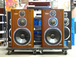
22. A result of use It works really smoothly. It traces easily a sound of cannon in "1812 Overture" of Tchaikovsky by Telarc Record. When by SME, there was noise at the strongest sound. Even if I turn down stylus force to 0.5g, there is no problem at all. I use cartridges of Ortofon, KONTRAPUNKT B, GT (with a transformer) currently by taking off from the shell. As a lead wire is soldered on an output pin, the mark might be remained when the lead wire is removed to replace stylus. I worry about if it is changeable. One or two mere weak points of this arm is to need a soldering for cartridge exchange. And the joint part of the cartridge shell and pipes joints are slightly weak. However, even if I twist it by hand, it is assumed to be all right. If I make it in general box form not a board, this part may add its strength. I can not make it by myself as you know. It is possible only when I buy a thick aluminum and sharpen it (carve it), but I do not have tools. All tools what I have are only a band-saw and a rigid drill. (It is a desk model that the drill goes down when the arm lifts down.) A problem of exchanging cartridge will be solved if I will attach a small joint pin to join with a cartridge in a place of a lead wire, but the number of the contact point will be increased. With my method, the contact point is only one place (pin/jack) to the place of pre-amprifier and it is also possible to omit. I do not add a pin Jack to a pre-amprifier. It comes out directly of a cable. 23. Please watch my pride audio system room that I brought up equally in this occation. Thank you very much for reading till the end of my story. Let's see you again sometime soon. |
|

|
|
 Used
Used Consigned
 Hold
Hold Reserved
 Sold Out
-
-

- Company profile
- Privacy policy
- Contact
- Newsletter back issues
- Hi-Fi Do live camera!
- Today's software
- Today's hardware
- New arrival alert system
- Japanese
-
Hi-Fi Do Online Newsletter
-
Payment methods

-
Shipping methods

-
Warranty policy

-
Shopping procedure

-
Hi-Fi Do Record Shops Softs, Audio parts and Tubes can ship overseas.Ordinary,we use EMS but for large order,we use SAL or Surface.For Asia,it cost 1,200JPY/1LP,900JPY/1CD.Please check at the shipping cost table for more detail.

-
Meaning of icons
